Time to read: 8 min read
Custom Keyboard PCB
# Main Resources
# QMK Firmware
I was lurking r/mk for half a year probably, and it never occurred to me that I could build my own custom keyboard, until I learned about QMK. QMK is an open source firmware for keyboards upheld by the community. It supports a bunch of different hardware, including Atmega, Attiny and some STM microcontrollers. It has an excessive (though not all-encompassing) documentation helping newcomers, and supports backlighting, tap-dance and other awesome features that you won't get with a home-brew Arduino program.
# Schematic
There's not incredibly many open source keyboards, but there are a few. Gondolindrim made the highest quality ones, the keyboards in the Acheron Project. In the QMK Discord he himself recommends newbs to take notice of the Tsuki, which has all the features and best practices. I've learnt many things just from studying his schematics. I especially appreciate that his work is full of overengineered solutions, like when he puts a Schottky-diode above the LDO to protect it from backwards current.
# Routing
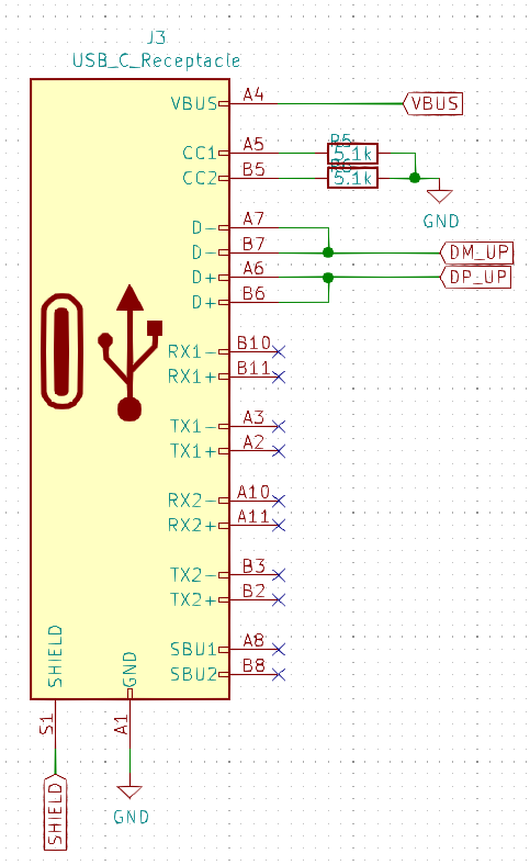
Here is a great resource about USB-C routing practices. USB-C in itself is relatively complicated, but by pulling down the CC lines with 5.1k resistors it gets converted to a standard 5 pin USB, which then is easier to handle. I found that the 16-pin connector variant is relatively easy to route and to solder.
# First prototype
I spent quite some time working on my first PCB, and I knew I wouldn't get everything right. But mostly I hoped to clear up a lot of things I wasn't sure about, and that I could get it to work in some way or another. In some sense I did have a previous prototype already in the form of the "BDN6" macro board, that I briefly mentioned in my first 3D printer adventures.
# Don't use STM32F103
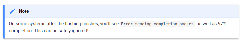
I went with an STM32F103R8C6 chip because I was somewhat familiar with it, and because it's what Bluepill uses, which is compatible with QMK. In hindsight it was a bad choice. The F103 doesn't have a USB bootloader from factory, like the F303, F072, and others do. (It also lacks 22Ohm series resistors and the 1.5k pullup on line D+ denoted on page 74 of the datasheet, as the others do, which is mildly inconvenient.) I did flash some sort of a maple bootloader on it with an ST-Link, but I never really managed to get QMK to work on it. My design included a led on PA13, which confirmed that the bootloader flashed fine. But flashing QMK resulted in this weird "97% completion" error every time, which according to Cannonkeys can be safely ignored (?). No matter how much I ignored the message, my computer just wouldn't recognize the keyboard as a HID device.
After about two days of this, I placed an order of STM32L072 chips, which do come with a USB bootloader. The L072 has the 22Ohm series resistors and the 1.5k pullup built in, and it is also capable of crystalless USB operation. Of all the SMD components, I hate soldering crystals the most, so I really hope I interpreted that feature right.
# ISO Enter Confusion
The ISO Enter key doesn't have good documentation, or at least I didn't find any. I inferred the switch placement under it via the swillkb plate builder.

::: tip ISO Enter switch placement Vertically, it's in the middle of the 2U height of the Enter key, and horizontally it's in the middle of the narrower, 1.25U wide bottom part of the key. :::
But only when my Tai Hao keycaps arrived, did I learn that the cherry switch underneath has to be upright. Basically, taking a 2U stabilizer together with the switch footprint (e.g. the whole BackSpace key), and rotating it 90 degrees won't work. The stabilizer does have to be rotated to be in a vertical position, but the switch doesn't. The cross profile stem on top of the switch is thicker in one orientation, and thinner in the other, so it only fits the keycap in two of four directions, if that makes sense. To illustrate:
# Plugging it in
Obviously, I didn't just plug the board into the computer without much thought. I actually broke out GND, +3V3, and +5V, so that I could easily test for short circuits. And when I was confident, I first connected it to 5V from a power supply to check for magic smoke. Then I measured the aforementioned voltages, and actually discovered a diode that was soldered on backwards, which was apparent, because the voltages didn't match. Only when everything checked out, did I connect it to my laptop.
# Conclusion of V1
V1 uncovered three times as many oversights and bugs as I had anticipated. Even though this sounds bad, I have gotten much more confident in what I'm doing, and I can definitely see the light at the end of the tunnel.
# Layout and Features of V2
After everything I've learnt, I corrected the schematic and rerouted the whole board. There's even some extra features that I included along the way, which I am going to discuss here. I have great hopes for V2, and I haven't ordered it yet, but I'm happy enough with it that I want to share it beforehand.

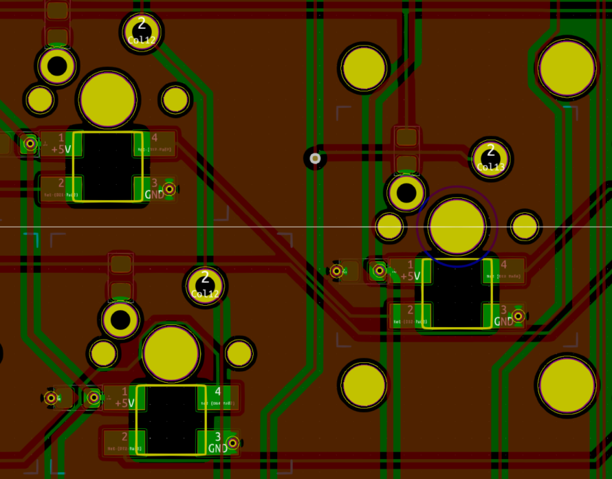
The image above of the top of the PCB was created with tracespace.io, which is open source, and generates awesome looking svg images. You just need to upload the same gerber files that you would send to the PCB manufacturer.
I decided to branch off of "the 75%" layout, which means it is tenkeyless, has the whole function row, and has the arrows compressed under "Enter". The top right corner supports a regular switch or an encoder. You can inspect it on Keyboard Layout Editor.
I wanted the whole PCB to fit entirely under the keycaps, partly to be slick, and partly because I embraced the challenge. The only exception is the USB-C connector, which sticks out on top. In contrast to that, I cut out enough place under the spacebar for a whole USB-A connector, where the receiver of my wireless mouse should fit. If it works as I planned, I'll be really proud of that! Although I'll admit that if I didn't have this bezel-constraint, I'd prefer to have the receiver on the right side for line of sight.
# USB hub
Designing a keyboard takes a huge amount of time and money, and the schematic of mine was strongly based on the open source Tsuki from the Acheron Project. For these reasons I wanted to have an extra quork that few others have done, but which is functional and practical for my own use case. And this is it!
Others have integrated USB hubs, but as far as I can tell, it hasn't become mainstream in the custom keyboard community. USB is more complicated than just combining data lines. No wonder that there's so many controller ICs to choose from. I went with the USB2514, partly because it's said to be a better modern one, and partly because I had access to it at Hestore, which is my favorite "local" electronics shop in Budapest. The only problem I have with it is the packaging, which is the hardest-to-solder part on my keyboard now. If I'll have issues with it, I think I will fall back to the FE1.1, because it generally seems easier to use, and it also requires less components around it. Actually, I'm reevaluating my choices as I'm writing this.
Since I only plan to use one USB downline on the STM chip, and the other on the wireless mouse receiver, I didn't bother setting up proper power management. My other reason for doing so is cost-effectiveness, and physical space. There's two passive components already, that I pushed on the other side of the PCB, despite my wanting to showcase everything on the bottom side. This compromise still bugs me when I think of it, but I don't think I could have fit power management components. Maybe if I remove the function row, but leave the space as a top-bezel, then I'd have room for these features, and stay in the form-factor of the Discipline.
# Back side of the PCB

The plan is to have (almost) all of the components on the back side, along with some design features, and to show it all off through an acrylic bottom plate. The huge fish logo is an homage to my hometown in Hungary, Baja, which is famous for the annual fish soup festival. The placement is lucky, as it doesn't cover any important silkscreen markings.
Hofstädter's law says that everything takes longer, than expected, even if one takes into account this law. It's a funny line that will resonate with most engineers. It certainly resonates with me, so I put that on there too.
# Plate

A USB-A connector is too high to fit between the PCB and the plate, so it had to be cut out from the plate. To make it sturdy, I had to disable the horizontal cutout under the space key. I'm curious to see what disadvantages I introduced there.